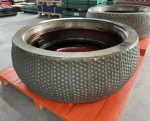
I have seen plants replace roller sleeves again and again, yet the wear rate stays the same. The real problem is that people treat “wear” like one thing. In a VRM, wear has several drivers, and they stack together. If I do not name the dominant driver first, I will keep paying for the wrong fix.
You can identify the root cause by matching the sleeve’s wear pattern and subsurface damage to the mill’s operating signals (vibration, power, bed stability) and process inputs (feed abrasiveness, moisture, tramp metal). In most cement VRMs, the dominant mode is two-body abrasion under very high contact pressure, and slip and rolling-point shift decide where the worst wear happens.
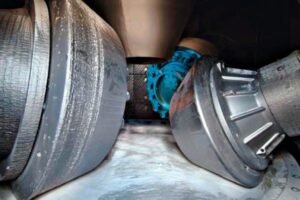
The hard part is that I cannot “look inside” a running VRM. Hot gas is around 200 °C, and the rising particle stream feels like a sand storm, with particle speeds that can reach about 60 m/s. So I rely on two things: what the mill tells me while it runs, and what the wear surface tells me after I stop and inspect. When I connect those two, the root cause shows up.
Why does my current roller sleeve suffer from abrasion, impact, or fatigue wear?
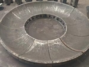
When I walk up to a worn sleeve on the floor, I first ask one simple question: “What did the surface go through, and what did the metal go through below the surface?” VRM rollers and table liners often see two-body abrasion under very high contact pressure, and I have seen reported values over 200 MPa. Under that pressure, even a small change in slip or bed thickness can move the high-stress zone and carve the profile in a new place.
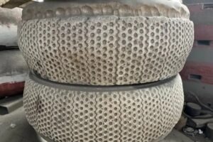
Abrasion shows as smooth profile loss and directional scratches; impact shows as chips, cracks, and broken hard phases; fatigue shows as pitting or spalling that starts below the surface and breaks out later.
In a VRM, tangential slip at the bed/roller interface is a major wear driver. I always remind teams that the table is driven, while the roller is effectively towed, so there is “built-in” slip even when everything looks stable. Slip often increases near the gap outlet, and it can also exist as a constant slip across zones because the kinematics are not perfectly rolling everywhere. That means I cannot explain wear only by hardness. I must also explain it by motion.
The rolling point is another key. It is the location where roller and table tangential speeds match. This point shifts with bed thickness, table speed, and wear-part geometry. When it shifts, the high-pressure zone shifts too. So the wear map changes even if I keep the same material. When wear changes shape, it is often the rolling point moving.
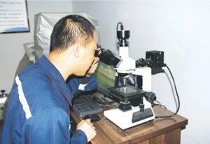
I also look beneath the surface when I can. In many abrasion-resistant overlays, microscopy shows subsurface damage where strain mismatch causes carbide fracture and decohesion below the worn surface. That hidden damage makes the surface loss speed up later. This is why some sleeves look “fine” for weeks, then suddenly lose mass fast.
To make this practical, I use a quick field table during inspection:
| Wear driver I suspect | What I see on the sleeve | What I often see in the mill data | What usually triggered it |
|---|---|---|---|
| Two-body abrasion under high pressure | Polished bands, long grooves, steady profile loss | Gradual power rise, stable vibration | High silica/quartz, high pressure, stable but harsh bed |
| Slip-driven abrasion | Localized banding near gap, uneven circumference wear | Power instability, slow vibration drift | Thin bed, poor feed distribution, table speed changes |
| Impact wear | Chips, edge break, star cracks, broken hardfacing | Sudden vibration spikes, alarms after events | Coarse feed, large lumps, tramp metal |
| Surface fatigue | Pits, spalls, “breakouts” that grow | Vibration grows with time, then jumps | Cyclic overload, bed instability, localized stress |
| Tribocorrosion | Darkened areas, undercutting, fast spall growth | More noise in signals, often tied to gas/moisture | Moist hot gas, alkalis, chlorides, sulfates |
I do not treat the table liner and roller sleeve as separate stories. If the roller shows one mode and the table shows another, I assume bed formation and slip are changing across the radius.
What early warning signs should I look for to detect abnormal wear in my VRM?
Most plants notice wear when product fineness drifts or when vibration becomes a constant fight. That is too late. Wear becomes self-reinforcing in a VRM. Profile loss changes bed formation. Bed changes shift the rolling point. Rolling point shift changes slip and local pressure. Then wear speeds up again. So I watch early signals that appear before geometry deviation becomes large.
The most reliable early warnings are rising vibration trends, growing motor power at constant throughput, wider pressure swings, and signs of unstable or thinning material bed; these usually appear before visible damage becomes severe.
I use a simple “trend first, event second” mindset. If I only react to alarms, I miss the slow drift that tells me the root cause is building. Here is what I track and how I interpret it in a practical way.
1) Vibration trend, not just peak value
If vibration rises slowly over days, I suspect profile change, rolling point shift, or bed instability. If vibration spikes sharply, I suspect impact events, tramp metal, or sudden bed collapse. I also compare vertical and horizontal components if I have them. A consistent directional rise often points to uneven wear around the circumference.
2) Power trend at constant throughput and fineness
If power increases while feed rate and fineness stay similar, friction and slip are often rising. That can happen when the bed is thinner, when the surface roughness changes, or when spalling increases local stress. I also watch separator settings and recirculating load, because a hidden shift there can fake a wear signal.
3) Grinding pressure stability
A stable bed usually gives stable pressure response. When the bed gets thin or unstable, pressure control hunts. That hunting adds cyclic loading, and cyclic loading is how surface fatigue starts. Once spalls form, local contact stress rises, and wear can accelerate in a nonlinear way.
4) Temperature and gas/moisture clues
If I see conditions that promote tribocorrosion, I assume the wear surface is weaker than its hardness number suggests. Moist hot gas plus aggressive chemistry like alkalis, chlorides, and sulfates can assist crack growth and undercut overlays. Then abrasion and fatigue damage propagate faster.
5) The “geometry signal” from operation
When rollers lose profile, the mill may need more pressure to hold the same product. The bed may shift outward or inward. The rolling point can move. Even if I cannot see inside, I can often infer geometry drift from how sensitive the mill becomes to small changes in feed or water.
To keep it structured, I use this quick checklist:
| Signal | What “normal” looks like | What “abnormal” looks like | Likely wear story |
|---|---|---|---|
| Vibration | flat or repeatable pattern | slow drift up or frequent spikes | drift = profile/slip; spikes = impact/bed collapse |
| Main drive power | stable for same tph | gradual rise or oscillation | rising friction, thinner bed, growing damage |
| Pressure control | smooth response | hunting, swings, frequent corrections | cyclic loading, fatigue risk, unstable bed |
| Product stability | steady fineness | fineness swings and more rejects | bed instability, separator interactions |
| Maintenance findings | small rebuild need | fast rebuild need, uneven zones | self-reinforcing wear loop underway |
In my experience, timely rebuilds before geometric deviation becomes large can save more than any single alloy change, because it stops the feedback loop that makes wear accelerate.
How can metal-ceramic composite technology reduce wear in my cement mill?
When people ask me about “better material,” I answer with three words: load, slip, chemistry. A VRM is not a simple abrasion rig. It is a high-pressure, mixed-mode wear system, and the dominant mode is usually two-body abrasion, but impact, fatigue, and tribocorrosion can take over fast when conditions drift. This is where metal-ceramic composite technology can change the outcome, because it does not rely on hardness alone.
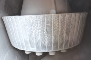
Metal-ceramic composites reduce wear by combining hard ceramic phases for abrasion resistance with a tough metal matrix that resists cracking and impact, so carbides or hard phases are less likely to fracture and fall out under high pressure and cyclic loading.
I have seen classic failure modes in hardfacing and high-chromium solutions: cracks that run through brittle zones, spalls that start under the surface, and hard particles that break or debond due to strain mismatch. Once hard phases break loose, the surface turns into a “self-feeding” abrasion process, because the broken particles become aggressive third bodies in the contact.
A well-designed metal-ceramic composite approach targets that chain reaction. The idea is not only to be hard. The idea is to keep the hard phase supported, anchored, and protected from brittle fracture. Under high contact pressures, I want the load to transfer through a structure that does not concentrate stress into one brittle network. Under cyclic loads, I want crack growth to slow down. Under impact, I want resistance to chipping. Under tribocorrosion, I want less undercutting and less fast crack growth at the surface.
Here is how I frame the benefit in engineering terms:
| VRM challenge | What fails in common solutions | What metal-ceramic composite aims to change | What I expect in practice |
|---|---|---|---|
| Two-body abrasion at >200 MPa | fast profile loss on “soft” zones | hard phase carries abrasion | slower mass loss, steadier profile |
| Slip-driven high shear | microcracking and particle pull-out | stronger phase support and bonding | less pull-out, slower groove growth |
| Impact and tramp metal | chipping and overlay cracking | tougher matrix blocks crack spread | fewer chips, less rapid geometry distortion |
| Surface fatigue | subsurface cracks grow into spalls | crack resistance and stress distribution | delayed pitting/spalling, smoother wear |
| Tribocorrosion | ضعف السطح وتسارع الشظايا. | تقليل التقليل من التقويض وتحسين التكامل | سطح أكثر ثباتاً تحت الغازات القاسية |
وهذا يناسب طريقة عملنا في شركة Dafang-Casting. نحن نركز على تقنية مقاومة التآكل المركبة من المعدن والسيراميك لأنها تمنحني هامش أمان أوسع عندما لا تكون المطحنة مثالية. في المصانع الحقيقية، تتغير التغذية وتتغير الرطوبة ولا يكون استقرار السرير مثاليًا دائمًا. غالبًا ما يكون نظام المواد الذي يقاوم التآكل والتشقق هو الفرق بين الصيانة المخطط لها والإغلاق المفاجئ.
وأقول للفرق أيضًا أن المواد ليست الرافعة الوحيدة. إذا كان الانزلاق وإزاحة نقطة التدحرج هما العاملان المحركان، فما زلت بحاجة إلى تثبيت السرير وتقليل التحميل غير المتساوي. تساعد الأكمام المركبة في ذلك، لكنها تعمل بشكل أفضل عندما لا تجبرها ماكينة التفريز على التلامس المستمر والتلامس بين المعدن والمعدن.
الخاتمة
في عملي، فإن أسرع طريقة للعثور على السبب الجذري لتآكل غلاف الماكينة VRM هي مطابقة أنماط التآكل والتلف تحت السطح مع اتجاهات التشغيل مثل الاهتزاز، والطاقة، واستقرار السرير. تعاني معظم ماكينات VRM الأسمنتية بشكل أساسي من تآكل جسمين تحت ضغط عالٍ جدًا، ويحدد الانزلاق وتحول نقطة التدحرج مكان تركز التآكل. عندما ينضم الصدم، والإجهاد، والتآكل القابل للتآكل، يمكن أن تتسارع وتيرة التلف بسرعة. هذا هو السبب في أنني كثيرًا ما أوصي بأكمام الأسطوانة المركبة المصنوعة من المعدن والسيراميك من Dafang-Casting لإطالة العمر الافتراضي وتقليل وقت التوقف عن العمل في ظل ظروف الأسمنت القاسية.