Every time I walk into a mill with a VRM vibration alarm and a fresh set of worn sleeves on the floor, I see the same fight. The roller needs hardness to stop abrasion, but it also needs toughness to survive impact and thermal stress. If the ceramic ratio is too low, wear eats the profile fast. If it is too high, cracks and spalling show up and ruin the gain.
For most VRM ceramic–metal composite roller sleeves, a practical “first-pass” sweet spot is about 20–35 vol% ceramic in the wear zone, and many plants land near 25–30 vol% when impact is moderate and abrasion is dominant.
I learned early that “more ceramic” sounds safe on paper, but the mill does not care about paper. It cares about bonding, dispersion, and where the impacts hit. So I start with a target range, then I pull it up or down based on the real failure mode I see on the sleeve face, the edges, and the dam ring area. If I get that part wrong, even the best material looks bad in the field.
How Does the Ceramic Percentage Affect the Service Life of My VRM Roller Sleeves?
Service life changes because ceramic raises abrasion resistance, but it also changes how the sleeve handles stress. When I increase ceramic, I usually see slower profile loss on the main wear track. At the same time, I watch for a new risk: microcracks and local spalling where impact and thermal cycling are strongest.
In VRM sleeves, higher ceramic content often extends wear life under abrasion, but the gain depends on dispersion and bonding; if cracking or spalling becomes the main failure, service life can drop even with higher wear hardness.
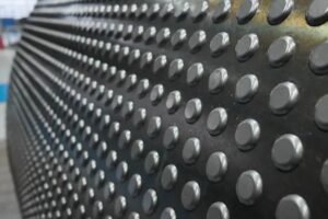
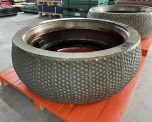
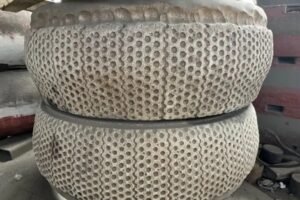
In my field notes, the most useful way to link ceramic ratio to service life is to separate “wear-controlled” life from “damage-controlled” life. Wear-controlled life means the sleeve simply wears down until grinding becomes unstable. Damage-controlled life means the sleeve fails early from cracks, edge chipping, spalling, or bond failure. Ceramic content helps the first case, but it can hurt the second case if I push it too far or if the ceramic is not placed in a smart pattern. I often explain it like this: ceramic controls the surface, while the metal controls the structure. If the sleeve is designed so a ceramic-rich layer covers the full working wear area, and the tougher metal supports impact loads under it, I can raise the ceramic fraction without inviting failure. A honeycomb or cell-like ceramic distribution does this well because it keeps coverage high but still gives metal “bridges” that carry shock. Below is the way I normally frame targets in plant language.
| Dominant field condition | Typical ceramic target in wear zone | What I watch first on inspections |
|---|---|---|
| Pure abrasion/erosion (hard feed, low tramp, stable bed) | 30–35 vol% | Wear track depth and profile retention |
| Mixed abrasion + impact (normal cement VRM reality) | 25–30 vol% | Edge chipping, fine cracks, local spalls |
| Impact/spalling dominant (tramp, unstable bed, frequent vibration) | 20–25 vol% | Spall pits, crack networks, debond lines |
Why Does Increasing Ceramic Content Improve Wear Resistance in My Mill?
When I look at a worn sleeve under simple magnification, the story is clear. Abrasive particles plow the surface. If the surface is mostly metal, it cuts and smears. If the surface has enough hard ceramic, the abrasives slide, fracture, or get deflected. That slows the wear track and helps the roller keep its grinding geometry longer.
More ceramic improves wear resistance because hard particles take the abrasive contact and protect the softer metal matrix, but only when particles are well-bonded and evenly dispersed.
Hardness is the obvious part, but the real control is load sharing. Ceramic particles, such as ZTA, can reach hardness levels far above typical alloy matrix hardness, so they act like micro armor plates in the wear zone. Still, armor only works if it is connected. If particles agglomerate, the cluster becomes a weak island. Under cyclic load, that island can loosen and pull out. After that, I get a void, then a crack starts at the edge of the void. This is why dispersion and wetting matter as much as the ceramic percentage. I also care about particle size and shape. Fine particles can pack well and reduce local stress peaks, but they also raise viscosity during processing and can trap porosity if the process is not controlled. Coarser particles can resist pull-out, but they can create higher stress concentration if the interface is weak. When I tune ceramic ratio, I am really tuning three things at once: surface hardness, interface strength, and the ability of the metal to carry impact. In mills with high quartz in the feed or high circulating load of hard particles, I can justify higher ceramic fractions, but only if the sleeve design keeps a tough metal path under the wear layer.
How Much Ceramic Do I Need to Prevent Cracking and Spalling in My Roller Sleeves?
Cracking and spalling are not solved by ceramic alone. They are solved by balance. When I see spalling, it often starts with poor bonding, pores, or ceramic clustering, then the crack grows under repeated impact. So the “right” ceramic amount is the highest amount I can use while keeping the sleeve tough enough and the interface strong enough.
If cracking and spalling are your main failures, start lower—often 20–25 vol% ceramic in the wear zone for ceramic–metal sleeves—and only increase after proving good bonding and low porosity in tests and early field runs.
When I troubleshoot a cracked sleeve, I do not start by blaming the ceramic ratio. I start by asking where the crack begins. If it begins at the edge, I suspect impact and bed instability. If it begins as a network on the wear track, I suspect thermal cycling and local stress concentration. If it begins at a pore or around a ceramic cluster, I suspect processing and dispersion. A high ceramic fraction can raise crack sensitivity because ceramics do not yield like metal. If the ceramic volume gets too high, the metal “ligaments” between particles become thin, and the structure loses its ability to absorb shock. This is similar to what people see in ceramic–epoxy systems when ceramic is pushed too high and voids rise, which then promotes microcracks when adhesion is weak. I see the metal version of this when interfacial bonding is not strong enough or when porosity is high. So my prevention plan is always a package: a controlled ceramic fraction, a distribution pattern that avoids large clusters, and a metal support structure that carries impact. If I must push ceramic higher for abrasion, I compensate with better bonding methods, controlled particle grading, and a geometry that avoids sharp stress raisers at the sleeve edges.
What Ceramic-Metal Balance Gives Me the Best Cost-Per-Hour Performance?
Cost-per-hour is not about the longest life in the lab. It is about stable grinding, predictable shutdown planning, and fewer emergency events. I have seen sleeves with very high ceramic that look perfect for wear, but they cause vibration from uneven wear or they spall at the edges and force an early change. That is expensive life.
The best cost-per-hour usually sits at a balanced middle: about 25–30 vol% ceramic in the VRM wear zone, with a tough metal support design, because it extends wear life without pushing crack risk and instability too high.
I estimate cost-per-hour with three parts that plant teams recognize right away. First is sleeve purchase cost. Second is changeout cost, which includes lost production. Third is “risk cost,” which is the unplanned shutdown cost when something goes wrong. Ceramic fraction affects all three. Raising ceramic may lower wear rate, so planned shutdowns move out. But if it raises spalling probability, risk cost rises fast. This is why I prefer to target a range that gives consistent behavior. I also like designs where ceramic coverage is full across the working wear area, but ceramics are arranged in cells so the metal can still bridge loads. That layout lets me keep abrasion resistance high without turning the whole wear zone into a brittle plate. If the plant has low tramp iron and stable bed, I can move toward the higher side. If the plant has frequent vibration, high feed size swings, or hard lumps, I stay lower and focus on toughness and stability first. Here is a simple decision table I use.
| Goal | Ceramic fraction move | What I improve at the same time |
|---|---|---|
| Longer life under abrasion | Increase toward 30–35 vol% | Dispersion control, bonding strength, porosity control |
| Stop early spalling | Decrease toward 20–25 vol% | Tough metal support, edge design, impact control |
| Reduce unstable wear pattern | Keep 25–30 vol% | Uniform distribution, consistent ceramic coverage, process stability |
How Does Ceramic Content Influence Grinding Stability in My Cement Plant?
Grinding stability depends on geometry retention and vibration behavior. Ceramic helps geometry retention because it slows wear. But if ceramic distribution is uneven, the roller can wear in patches, and the mill can feel it as vibration, noise, and higher power swings.
Ceramic content improves grinding stability when it keeps the roller profile stable, but too much ceramic or poor dispersion can create patchy wear and spalling that increases vibration and process swings.
In daily operation, the mill does not “measure” ceramic content. It reacts to the results. If the sleeve holds a smooth, even wear track, the bed stays steady and the mill runs calmer. If the sleeve starts to spall or develop uneven wear islands, the bed becomes less predictable. Then I see more vibration events, more roller lifting events, and more control actions from the operators. Ceramic content plays into this because it changes the stiffness and the way the surface breaks in. A ceramic-rich surface can resist wear strongly, but if it contains clusters or weak-bond pockets, those pockets can open up suddenly. That creates local pits. Pits disturb the bed. Disturbed bed causes more impact. More impact makes pits grow. This loop is why I keep saying dispersion and bonding matter as much as ratio. I also pay attention to where the ceramic is placed. If the design ensures ceramic coverage across the full working wear area, the wear rate is more uniform. If ceramic coverage is partial or inconsistent, the roller can develop a “two-material” wear pattern. That is a common path to vibration because the roller does not maintain a consistent contact pattern. So for stability, I would rather have a slightly lower ceramic fraction that is uniform and well bonded than a higher fraction that is patchy.
Can I Customize the Ceramic Ratio Based on My Raw Material Conditions?
Yes, and I think you should. I do not believe in a single ratio that fits clinker, slag, limestone, and coal the same way. The raw material changes abrasion severity, impact frequency, temperature profile, and the probability of foreign objects. All of those change the best ceramic-metal balance.
You can customize ceramic ratio based on your feed abrasiveness and impact risk: push higher for abrasion-dominant materials, and pull lower when impact, spalling, and vibration events dominate.
When I set up a customization plan, I start with the failure mode that costs the plant the most. If the plant loses life because sleeves wear flat too fast, the material is telling me to add more ceramic or improve ceramic hardness and coverage. If the plant loses life because sleeves crack at the edges or spall in chunks, the material is telling me to protect toughness and interface strength first. I also ask about the feed. High quartz and hard minerals push me toward higher ceramic. High moisture and unstable bed push me toward lower ceramic because impact rises. Coal mills and raw mills can also have different thermal and impact behavior than finish cement VRMs. A practical way to do this without guesswork is a short test matrix. I often propose a set like 20/25/30/35 vol% in the wear zone, with the same ceramic type and the same processing controls. Then we run a short field validation and compare wear profile, vibration trend, and any crack initiation marks. This approach matches what I have learned from polymer composite systems too. The “optimum” shifts up when dispersion and bonding are strong, and shifts down when agglomeration and pores show up.
What Happens If the Ceramic Content in My Roller Sleeve Is Too High?
When ceramic content is too high, the sleeve can become sensitive. It may show higher porosity, weaker metal continuity, and higher stress concentration. In the mill, that often shows up as microcracks, edge chipping, spalling pits, or sudden chunks breaking free.
If ceramic content is too high, you can get brittle behavior: higher crack sensitivity, spalling, and uneven wear, especially when bonding is weak or ceramic clusters form.
I have seen this pattern enough that I treat it as a warning sign, not a surprise. First, the sleeve may look excellent in early wear because the surface is hard. Then, after enough impacts, small cracks start at weak spots. Those weak spots are often pores, cluster boundaries, or interface regions with poor wetting. Once the crack network forms, small pieces can spall out. After spalling begins, wear accelerates because the surface becomes rough and the bed becomes unstable. This is also when operators start chasing vibration and pressure swings. If the ceramic is too high, it can also complicate manufacturing because viscosity rises and dispersion becomes harder. That can increase defects. So “too high” is not just a number. It is a combination of fraction plus structure plus quality control. This is why I like a ceramic distribution design that keeps ceramic coverage high but avoids turning the whole cross-section into a ceramic-rich brittle zone. If I need high wear resistance, I would rather concentrate ceramic where it is needed and keep a strong metal support under it.
How Do I Know If My Current Ceramic Ratio Is Causing Uneven Wear?
Uneven wear shows itself in the profile, the vibration trend, and the surface pattern. I can usually tell from a combination of physical inspection and operating data. If ceramic ratio is part of the cause, I often see patchy wear islands or local pull-out zones linked to dispersion issues.
You can suspect ceramic-ratio-related uneven wear when you see patchy wear islands, localized pull-out pits, and a rising vibration trend that matches the growth of surface roughness rather than normal gradual wear.
In practice, I use a simple checklist during inspections. I look for repeated patterns at the same circumferential positions, which can hint at distribution problems from casting or composite formation. I look for pits that expose a different substrate color or texture, which can indicate particle pull-out. I also compare center wear to edge wear. If edges chip while the center looks fine, it often means impact and stress are winning over toughness, which can happen when ceramic content is too high or when metal support is not enough. If the surface shows a “pepper” texture of many small pits, I suspect widespread particle pull-out or micro-porosity. Then I go back to dispersion quality and bonding tests. At the same time, I do not ignore process causes. Feed size swings, unstable bed, and high vibration can create uneven wear even with a perfect sleeve. So I always pair the physical evidence with data like vibration history, differential pressure trends, and any reported tramp events. If the uneven pattern is tight and localized, it often points to material distribution. If the uneven pattern is broad and tied to process events, it often points to operating conditions first.
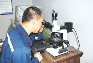
What Tests Can Verify the Ceramic Dispersion Quality in My Composite Sleeves?
Dispersion quality is the difference between “high ceramic works” and “high ceramic fails.” I want to see uniform particle spacing, low clustering, and strong interfaces. I also want to see low porosity. So I choose tests that show structure, bonding, and defects.
To verify dispersion quality, use sectioning plus microscopy for particle clustering, image analysis for uniformity, porosity measurement, and interfacial checks; then confirm with wear and impact tests on representative samples.
When I work with a plant or a lab team, I ask for a test set that answers clear questions. “Are particles uniform?” “Is the interface strong?” “Are pores present?” A practical set includes macro-etch inspection on cross-sections to reveal distribution patterns, followed by optical microscopy and SEM on key zones like the main wear track and edges. I also like quantitative image analysis, because photos alone can hide clustering if people choose the best area. For porosity, I want a method that is consistent across batches, such as density-based porosity estimation or micro-CT on smaller coupons if available. Then I use hardness mapping across the wear layer to ensure the ceramic-rich region is continuous and not broken. After structure checks, I still want functional tests. A short abrasion test helps compare wear rates, and a simple impact or thermal shock style test helps flag brittle behavior early. In polymer composite work, people see that high ceramic can raise voids and microcracks when adhesion is poor, and I take the same lesson into metal-ceramic sleeves. If pores and clusters rise as I increase ceramic, I stop increasing and fix the process first.
How Can I Get Technical Guidance on Choosing the Right Ceramic Ratio for My Mill?
Guidance should not be a generic brochure. It should start with your failure mode, then your material conditions, then your operating stability. I can give fast direction if I have your wear evidence and a few key operating details. After that, I like to propose a short ratio matrix and a validation plan.
The fastest way to choose the right ratio is to match ceramic fraction to your dominant failure mode, then run a short test matrix (for example 20/25/30/35 vol% in the wear zone) and confirm with wear profile and vibration data in your mill.
When I support a plant, I usually ask for three things and I can move quickly. First, photos of the worn sleeves with notes on where failures start. Second, basic operating context: feed material type, typical vibration behavior, any tramp events, and whether the mill runs stable or hunts. Third, any past sleeve history: life hours, repair history, and how the wear profile changed over time. With this, I can suggest a starting ceramic range and a distribution approach. For many cement VRMs, I start around 25–30 vol% ceramic in the wear zone, then adjust. If the plant is abrasion-dominant and stable, I move toward 30–35 vol%. If the plant is impact-dominant with spalling, I move down toward 20–25 vol% and reinforce the metal support strategy. I also push for a design that gives full ceramic coverage on the working wear area, like a honeycomb distribution of ZTA ceramic particles, because it can keep wear resistance high while the tougher metal carries impact loads. Finally, I always ask for verification tests on dispersion and porosity, because that is where “good ratio” turns into “good results.”
Kesimpulan
In my experience, the “best” ceramic ratio is not a single number. It is a range that matches your failure mode and your mill stability. For VRM ceramic–metal sleeves, I usually begin at 20–35 vol% ceramic in the wear zone, and I often land near 25–30 vol% for the best balance. If you want a safer and faster path, I recommend working with Dafang-Casting (wenetting) to set a ratio matrix and validate it with dispersion tests and short field runs.