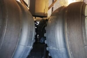
When a vertical roller mill runs well for months and then a roller sleeve suddenly cracks, the whole plant feels it. I have seen this stop kilns, delay shipments, and destroy maintenance budgets. Cracks often look like accidents, but they almost always have clear root causes in materials, load, heat, alignment, and monitoring.
VRM roller sleeves usually crack due to a combination of material or heat-treatment weakness, high dynamic or thermal loads, stress concentration from poor fit or machining, and uneven operating conditions such as vibration, low material bed, or poor lubrication. A structured root cause analysis can prevent repeat failure.
I always tell my team that a cracked sleeve is not just bad luck. It is a message from the mill. When I read the wear pattern, the crack path, and the operating history together, I can usually see if the real problem came from design, material, operation, or maintenance. Then we can change the right thing instead of just buying another sleeve and hoping for the best.
What operating conditions in my mill are most likely causing sleeve cracking?
When a sleeve cracks, most people first blame the part supplier. In my work, I often find that the mill runs out of its safe operating window for long periods, and this slowly builds damage.
The operating conditions most likely to cause sleeve cracking are high vibration, frequent load changes, low material bed, high differential pressure, and long periods of overload or under-lubricated running. These conditions create high cyclic stress and thermal shock on the roller sleeve.
Key operating factors I always review
I start with the DCS trends and daily reports. I check how often the mill trips, how often it runs at low or high feed, and how stable the differential pressure is. If the operators keep changing the feed and grinding pressure, the sleeves see repeated loading and unloading, which creates fatigue. When the material bed is low, the rollers hit the table harder, and the impact goes directly into the sleeve surface.
Simple checklist of risky conditions
| Operating factor | Risk for cracking | What I check first |
|---|---|---|
| Material bed height | Local impact and pitting | DP trends, feed fluctuations |
| Vibration level | Fatigue from cyclic stress | Vibration history, alarm records |
| Load swings / trips | Thermal and mechanical cycling | Start/stop frequency, process disturbances |
| Lubrication condition | Tilt and misalignment | Oil pressure, temperature, filter history |
When I combine this data with the damage pattern on the sleeve, I can see which operating factor is most likely the main driver.
How can I identify whether my roller sleeve failure is due to impact or thermal fatigue?
I often see people guess the cause based only on the crack position. This is risky. Impact fatigue and thermal fatigue leave different “signatures” on the surface and in the crack path.
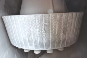
Impact fatigue usually leaves shelling, pitting, or step-like cracks starting at the surface in heavy load zones. Thermal fatigue often shows fine network cracks, color changes, and crack paths that follow heat-affected areas, not only impact zones.
How I read the crack pattern
When I inspect a failed sleeve, I first look at the contact area. If I see craters, matte “pounded” surfaces, and chunks missing near the feed or high load side, I suspect impact. The cracks often start at the surface and step inward. In thermal fatigue, I usually see fine, repeated crack lines like a net, often together with discoloration from overheating or sudden cooling, for example after water spray issues or sudden feed changes.
Visual clues I use in the field
| Feature | Impact fatigue sign | Thermal fatigue sign |
|---|---|---|
| Surface texture | Pitting, dents, broken edges | Fine checking, crazing, hairline cracks |
| Crack origin | At high-load contact spots | In zones with color change or hot spots |
| Crack direction | Often along rolling direction | Often cross-hatched or network-like |
| Associated history | Hard foreign bodies, low bed, overload | Spray changes, hot feed, frequent stops/starts |
I also look at cross-sections if available. Subsurface crack branching under a hard surface shell can confirm repeated impact, while oxidation marks and intergranular cracks in heat-affected zones point to thermal fatigue.
Are my current materials or heat-treatment processes contributing to cracking issues?
Many plants stay with the same alloy and supplier for years even when they keep seeing similar crack modes. In my experience, this usually means the material or heat treatment does not match the actual duty.
Yes, material and heat-treatment choices can strongly increase cracking risk. If the sleeve is too hard and brittle, has large carbides, or has uneven hardness due to poor quenching or tempering, micro-cracks form and grow into visible fractures under normal mill loads.
What I check in the material itself
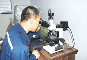
I look at hardness profiles through the thickness. If there is a very hard outer layer with a sharp drop inside, this often means high residual stress. I also review microstructure photos if the supplier can provide them. Large, continuous carbides at grain boundaries act like crack starters. Poor tempering can leave untempered martensite that is very brittle.
Simple material / heat-treatment review table
| Item to review | Warning sign | Possible action |
|---|---|---|
| Bulk hardness | Too high with no toughness data | Re-specify lower hardness with higher toughness |
| Hardness distribution | Strong gradient, sharp transitions | Ask for more uniform through-section profile |
| Microstructure | Coarse carbides, porosity, segregation | Improve alloy design, casting process |
| Heat-treatment records | Missing or inconsistent data | Require traceable heat-treatment parameters |
When I see repeat failures with the same material, I work with a supplier who can adjust alloy design and heat treatment to move from “maximum hardness” to “balanced hardness and toughness”.
How does insufficient toughness affect the lifespan of my VRM roller sleeves?
Many purchase specs still focus mainly on hardness. I have seen plants insist on very high HRC values and then wonder why sleeves crack early even though wear looks low.
Low toughness makes the sleeve sensitive to cracks from impact, vibration, and residual stress. The sleeve may resist abrasion well but fails early by cracking, which shortens real service life more than slightly higher wear would.
Why I never look at hardness alone
If a roller sleeve behaves like glass, a small defect or a single big impact can start a crack. With higher toughness, the same defect might blunt or stop. I like to see Charpy impact data or other toughness indicators together with hardness. When the mill processes clinker with large lumps, slag, or tramp metal, the need for toughness becomes even stronger.
Balancing hardness and toughness
| Property | Too low effect | Too high effect | My target in practice |
|---|---|---|---|
| Hårdhed | Fast wear, short wear life | Brittle cracking, spalling | Enough for wear, not extreme |
| Toughness | Cracks grow easily, sudden break | Better crack arrest, safer failure mode | As high as alloy system allows |
In my projects, sleeves with slightly lower hardness but far better toughness often give longer “crack-free hours”. The plant gets stable operation and predictable wear instead of surprise breakage.
What role does raw material hardness play in the cracking of my grinding rollers?
People sometimes treat all feeds the same. In my experience, the hardness and size of the feed material change the way loads reach the roller sleeve.
Hard and large raw materials increase local contact stress and impact, especially with low bed height. This accelerates surface fatigue and can start cracks even when sleeve material is good, especially near the feed and nozzle ring zones.
How I connect feed properties to cracks
When a plant changes from soft limestone to hard clinker or slag but keeps the same roller design and settings, I often see new crack patterns. Hard particles press into the sleeve surface and create stress peaks. If the feed has many coarse particles, they hit the rollers with higher impact energy. This is worse when feed is unstable or when hot material comes directly under the roller.
Linking feed to damage zones
| Feed property | Effect on sleeve surface | Typical crack zone |
|---|---|---|
| High hardness (e.g. slag) | Higher contact stress, micro-pitting | Middle of track, high load ring |
| Large lump size | Strong single impacts | Leading edge, feed side |
| Tramp metal / foreign | Deep dents, sub-surface cracks | Isolated spots with severe local damage |
When I see cracks mainly in zones that match hard material contact, I know I must either upgrade sleeve material and toughness or adjust operating conditions, or both.
How can I check if my mill vibration is accelerating crack formation in my sleeves?
I have rarely seen a cracked sleeve in a mill that runs truly smooth. High vibration does not always cause cracks alone, but it almost always speeds up damage.
You can check the role of vibration by reviewing vibration trends, correlating peaks with crack locations, and inspecting bearings, alignment, and foundation stiffness. Persistent high vibration strongly accelerates fatigue crack initiation and growth in sleeves.
How I link vibration data and sleeve damage
I look at vertical and horizontal vibration values on the roller and gearbox. If the vibration stayed high over months before failure, I treat it as a major factor. I then match the main vibration frequency to possible causes such as imbalance, looseness, or process instability. I also talk with operators about when alarms occur, for example during feed changes or separator adjustments.
Vibration clues I use
| Observation | Possible cause | Effect on sleeves |
|---|---|---|
| 1× running speed vibration | Imbalance, uneven wear | Cyclic bending of roller and sleeve |
| High random broadband vibration | Loose parts, poor foundation | Shock loads, changing contact conditions |
| Vibration spikes with feed dips | Process instability | Repeated impact and unloading of bed |
When vibration is high and stable, even small internal defects in the sleeve can grow into large cracks much faster than expected.
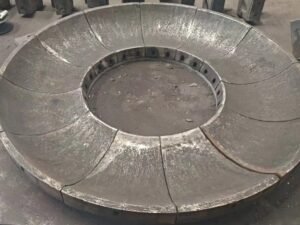
Why does uneven wear increase the risk of cracking in my roller sleeves?
Many people see uneven wear only as an efficiency problem. From what I have seen, it is also a serious crack risk.
Uneven wear creates local high spots and thin sections in the sleeve. These cause stress concentration, bending, and abnormal contact with the table, which can turn harmless micro-cracks into through-cracks much sooner.
What uneven wear tells me
When I inspect a worn sleeve, I measure thickness at several points. If one side loses much more material, that side sees higher stress. The roller can tilt slightly under load and press that side into the material bed harder. If the sleeve is thinner there, the same load gives higher stress in the material and around any defects.
Typical uneven wear patterns
| Brugsmønster | Likely cause | Crack risk zone |
|---|---|---|
| One-side heavy wear | Misalignment, tilt, poor feed | Thin side, transition to thick zone |
| Ring or band wear | Material distribution issues | Edge of wear band |
| Localized deep groove | Foreign body, nozzle ring issue | Groove edge, subsurface under groove |
To reduce crack risk, I push for better feed distribution, regular measurement of wear profiles, and timely rotation or replacement before the thin side becomes dangerous.
Can metal-ceramic composite technology help me eliminate cracking problems?
Many plants ask me if metal-ceramic composites are only about better wear. In my work with these materials, I have seen that they can also strongly reduce crack problems when designed well.
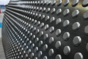
Yes, modern metal-ceramic composite sleeves can reduce cracking risk by combining a tough metal matrix with hard ceramic zones. When designed and bonded correctly, they offer high wear resistance with improved crack resistance compared to traditional high-Cr castings.
Why I moved many projects to metal-ceramic sleeves
Traditional high-Cr sleeves often chase hardness at the cost of toughness. With metal-ceramic technology, I can place very hard ceramic only where abrasion is highest while keeping a tougher steel matrix to carry impact and bending loads. The key is a strong metallurgical bond so there is no ceramic falling or interface cracking. At Dafang-Casting, we focus on this bond and on matching the composite layout to the real contact pattern of each mill type.
What I look for in a composite solution
| Feature | Why it matters | What I ask the supplier for |
|---|---|---|
| Tough metal matrix | Absorbs impact and vibration | Proven impact test data |
| Ceramic distribution | Targets high wear zones | Design drawing and track-by-track layout |
| Bond quality | Avoids ceramic spalling | Cross-section photos, long-term cases |
With a good design and correct fit, composite sleeves can run longer without cracks and give a more stable life curve.
How do I evaluate whether my operating parameters are causing thermal shock?
I have seen mills that “look” stable but still suffer from thermal fatigue cracking. The hidden cause is often repeated thermal shock from quick changes in temperature or load.
You can evaluate thermal shock risk by checking how fast and how often feed temperature, gas temperature, and mill load change, especially during start-up, shutdown, and upset conditions. Large, rapid changes create thermal gradients that start thermal fatigue cracks.
What I study in operating data
I review trends of inlet gas temperature, outlet temperature, feed moisture, and spray water if used. I watch how these change in the first minutes of start-up and after trips. If the temperature jumps or drops quickly while the roller surface is already hot or cold, I know the sleeve face and core may be at very different temperatures, which causes high thermal stress.
Parameters I focus on
| Parameter | Risk sign | Possible action |
|---|---|---|
| Inlet gas temperature | Sudden spikes or drops | Smoother burner and fan control |
| Water spray / cooling | On–off cycling with large swings | Adjust control logic or nozzle setup |
| Load during start-up | High load before thermal stabilization | Step load up more slowly |
I also ask operators about upset cases like blockages or sudden feed changes. These often create the worst thermal shocks, even if average trends look fine.
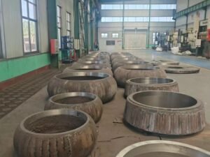
What upgrades or customizations can extend the crack-free life of my VRM roller sleeves?
Once we know the root causes, we can move from firefighting to upgrades. In many plants I work with, a mix of design, material, and monitoring changes gives the best result.
You can extend crack-free life by upgrading to tougher or metal-ceramic sleeves, improving sleeve-to-hub fit and machining, optimizing operating parameters, and adding regular vibration and crack monitoring with planned inspections.
Types of improvements I usually propose
First, I check the mechanical interface. Poor machining accuracy or loose fit between sleeve and hub can cause stress peaks; improving tolerances and contact surfaces removes these hidden stresses. Second, I review material and heat-treatment options and often move to metal-ceramic composite designs. Third, I work with the process team to stabilize the material bed, reduce vibration, and avoid thermal shock. Finally, I set up a clear inspection and monitoring plan.
Upgrade options at a glance
| Area | Typical upgrade | Effect on cracking risk |
|---|---|---|
| Sleeve design | Metal-ceramic composite, higher toughness | Better crack resistance and wear life |
| Machining / fit | Improved tolerances, better contact area | Reduced stress concentration |
| Operation | Stable bed, lower vibration, smoother heat profile | Less fatigue and thermal shock |
| Monitoring | Vibration, NDT, inspection schedule | Early crack detection, safer replacement |
With these steps, I have seen mills move from frequent unexpected cracks to long, predictable, crack-free campaigns.
Konklusion
Cracked VRM sleeves are not random events. They are the result of how material, design, and operation come together in real service. When I read the wear pattern, vibration history, thermal behavior, and material data together, I can remove the root causes instead of just changing parts. If you want sleeves with higher toughness, better impact resistance, and long crack-free life, I recommend working with us at Dafang-Casting (wenetting) to design a metal-ceramic composite solution that matches your mill and your raw materials.