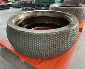
In the plant, I often saw the same problem repeat. A roller sleeve looked fine on the outside, then a crack line showed up, then spalling started, and the shutdown followed. The painful part was not only the cost. It was the lost stability. If I treat “composite” as a simple coating glued to steel, I will keep getting the same failure. That is the trap.
Metal–ceramic bonding works because the metal and ceramic do not just “stick.” They connect through diffusion, chemical bonds, and controlled interface reactions. When this interface is built well, the sleeve can carry load, resist crack growth, and keep wear stable for a longer time.
If I only remember one idea, it is this. The interface is the product. The ceramic is not useful if the bond cannot move stress into the metal. So I need to understand how the bond forms, how it fails, and how I can judge it before I install the sleeve.
How Does Metal-Ceramic Bonding Actually Improve the Lifespan of My VRM Roller Sleeves?
When I compare sleeves, I do not start from hardness. I start from failure mode. A VRM sleeve dies early when local stress rises, cracks start, then pieces break off, then wear gets uneven, then vibration increases. Bonding technology helps because it makes the wear layer act like part of the sleeve body, not a weak skin.
Metal–ceramic bonding improves lifespan by letting the interface transfer load instead of blocking it. If the bond is strong, the ceramic phase takes abrasion, and the metal phase takes impact and bending. That sharing of work slows down crack growth. It also keeps the wear surface more even, so the mill runs smoother. I also see a practical effect: stable wear means fewer process adjustments, and fewer hot spots on the table and rollers.
In real terms, the science shows up as three controls that matter in a VRM: stress distribution, crack path control, and wear stability. If bonding is weak, cracks run along the interface like a zipper. If bonding is strong, cracks must cut through a tougher path, and they lose energy.
| What kills sleeve life | What true bonding changes | What I see in operation |
|---|---|---|
| Interface peel or delamination | Load transfers across interface | Less sudden spalling |
| Fast crack growth from impact | Crack path is deflected and slowed | Fewer shock-related chips |
| Uneven wear and vibration | Ceramic is held firmly and wears steadily | More stable vibration trend |
| Heat cycling damage | Thermal mismatch is managed by design | Less edge damage after stops |
Why Does the Ceramic–Metal Interface in My Wear Parts Resist Cracking and Spalling?
Cracking and spalling usually start where stress is highest and toughness is lowest. In many failed parts I handled, the weak point was not the ceramic itself. It was the boundary. If the interface is only adhesion, stress concentrates there, and the first microcrack grows fast.
A good interface resists cracking because it is built with chemical bonds and reaction layers, not just contact. Thin interfacial products, like oxides, spinels, or carbides formed in a controlled way, can anchor the ceramic to the metal. At the same time, the interface must not be too brittle. So the best designs balance strength and toughness by controlling thickness, chemistry, and cooling.
Another key is thermal expansion compatibility. Metal and ceramic expand differently. If I ignore that, I lock in residual tensile stress during cooling, and tensile stress helps cracks grow. If I manage it, often by choosing the right alloy and using graded transitions, I reduce the stored stress. Then the interface can survive heat cycles, mill starts, and load swings.
| Interface feature | What it does to cracks | Why it reduces spalling |
|---|---|---|
| Chemical bonding / reaction layer | Stops sliding at the boundary | Prevents peel-off failures |
| Thermal expansion matching | Lowers residual tensile stress | Reduces cooling cracks |
| Graded transition zone | Spreads stress over distance | Avoids sharp stress jumps |
| Tough metal support | Absorbs impact energy | Prevents brittle break-off |
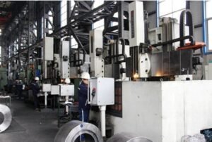
How Do Ceramic Particles Bond With the Metal Matrix in My Grinding Rollers?
In manufacturing, the bond forms when the metal phase can wet, react with, and lock onto the ceramic phase. If the metal cannot wet the ceramic surface, it will pull back like water on oil, and gaps stay. Those gaps become crack starters later.
Ceramic particles can bond with the metal matrix through four main mechanisms working together. First is metallurgical diffusion, where atoms move across the boundary at high temperature. Second is chemical bonding through interfacial reaction products, which act like a bridge between two different materials. Third is mechanical interlocking, where molten or softened metal penetrates surface roughness, pores, or engineered textures in the ceramic. Fourth is solidification locking, where the metal freezes around the ceramic in a way that clamps it.
Industrial processes like brazing and liquid-phase sintering support these mechanisms because they introduce a liquid metal phase that can wet and flow. Alloy chemistry matters because small additions can change wetting at the nanoscale. In practice, this is why two “composites” can look similar in a brochure but behave very differently in a mill.
| Bonding route | What must go right | What goes wrong if it fails |
|---|---|---|
| Wetting + liquid flow | Alloy wets ceramic surface | Voids, weak spots, early spall |
| Interfacial reaction products | Layer is strong but not too thick | Brittle layer, crack runs fast |
| Diffusion | Time and temperature are controlled | No true bond, only contact |
| Mechanical interlocking | Surface structure is present | Particle pull-out under load |
What Makes Metal-Ceramic Composite Rollers Stronger Than Traditional High-Chrome Rollers?
High-chrome iron gives hard carbides, so it resists abrasion well. But it is often limited by brittleness. In my experience, this brittleness shows up when the mill sees impact, tramp metal, or big feed swings. The sleeve does not only wear. It breaks.
A metal–ceramic composite can be stronger in service because it is not trying to make one phase do everything. The ceramic phase provides very high hardness and abrasion resistance. The metal matrix provides toughness, crack resistance, and load support. If the bond is real, the interface transfers stress, so the ceramic does not act like loose stones in a weak cement. It acts like a reinforced structure.
The strongest advantage is not peak hardness. It is damage tolerance. If an impact happens, the metal matrix can deform a little and absorb energy. That reduces the stress spike in the ceramic phase. Also, if a microcrack starts, a well-designed interface and mixed microstructure can deflect it and slow it, so the crack does not turn into a chunk spall.
| Property in the mill | High-chrome roller | Metal-ceramic composite roller |
|---|---|---|
| Abrasion resistance | Hoog | High to very high |
| Impact tolerantie | Often limited | Higher when bonding is strong |
| Crack growth behavior | Can be fast | Often slower and deflected |
| Failure mode | Sudden spall / break | More gradual wear if designed well |
How Can This Bonding Technology Reduce My Mill’s Maintenance Frequency and Downtime?
Maintenance frequency is not only driven by wear rate. It is driven by failure surprises. I have seen plants that planned a wear change, but instead they faced a crack event, a spall event, and an unplanned stop. That is where bonding technology pays for itself.
Bonding reduces downtime by keeping the wear surface stable and by lowering the chance of sudden piece loss. If the interface is strong, ceramic does not peel, studs do not drop, and spalling is less likely. That means vibration stays more stable, the mill needs fewer emergency interventions, and the spare strategy becomes easier. I also see fewer secondary damages. When a sleeve spalls, it often damages the table liner, the separator balance, or the hydraulic system because vibration rises.
Over time, fewer stops also reduce thermal cycling damage. Every stop and restart adds stress. If bonding and stress design are good, the sleeve survives those cycles better. That pushes maintenance from “reactive” to “planned.”
| Downtime driver | How bonding helps | Practical result |
|---|---|---|
| Unplanned spalling | Prevents interface peel | Fewer emergency stops |
| Vibration from uneven wear | Keeps wear uniform | Longer stable running window |
| Secondary damage after failure | Reduces sudden break-off | Lower total repair scope |
| Frequent inspection work | Predictable wear pattern | Less man-hour pressure |
Why Does My Coal Or Raw Mill Benefit From Metal-Ceramic Composite Wear Parts?
Coal and raw mills have their own wear signature. Coal often brings impact from foreign objects and sudden load swings. Raw material brings mixed abrasiveness, moisture changes, and sometimes sticky bed behavior. In both cases, I need a wear part that can resist abrasion without becoming fragile.
Metal–ceramic composite wear parts help because they combine abrasion resistance with better toughness. Coal milling benefits from impact resistance because the metal matrix can take shock and protect the ceramic phase. Raw milling benefits from stable wear because a stable surface supports bed formation and stable grinding pressure. If the surface breaks into pits by spalling, I lose control of the grinding zone, and power and vibration rise.
Also, the composite approach can be tuned. I can select ceramic fraction, particle size, matrix alloy, and transition layers based on feed and operating pressure. That adjustability is hard to achieve with a single high-chrome material choice.
| Mill type | Main risk | Why composite helps |
|---|---|---|
| Coal mill | Impact + tramp metal | Tough matrix absorbs shock |
| Raw mill | Mixed abrasion + process swings | Stable wear surface, less spall |
| Both | Thermal cycling during stops | Managed residual stress and interface design |
How Does This Bonding Technology Enhance Impact Resistance In My Roller Sleeves?
Impact resistance is not only a metal property. It is a system property. If the ceramic phase is bonded poorly, impact causes local separation first. That separation becomes a crack starter, then a spall. So impact resistance depends on whether the interface can keep carrying load during shock.
Bonding enhances impact resistance by enabling load transfer and energy sharing. During impact, stress waves travel through the structure. A strong interface reduces wave reflection and reduces stress concentration at the boundary. The metal matrix can deform slightly and absorb energy. The ceramic phase stays supported, so it does not see a high tensile spike that would trigger brittle fracture.
Residual stress design also matters. If cooling creates tensile stress near the surface, impact plus tensile stress is a bad mix. Controlled cooling, graded layers, and matched thermal expansion can keep the surface in a safer stress state. In practice, this is why two sleeves with the same “hardness” can behave very differently after a few shock events.
| Impact-related feature | Why it matters | What I look for |
|---|---|---|
| Strong wetting and chemical bond | Stops interface opening | No early micro-gap damage |
| Tough matrix alloy | Absorbs shock energy | No brittle ring cracks |
| Graded transition | Prevents sharp stress jump | No edge chipping pattern |
| Residual stress control | Reduces tensile stress risk | Stable performance after stops |
What Factors Affect The Bonding Quality Of My Metal-Ceramic Composite Rollers?
Bonding quality is not one parameter. It is a chain. If one link is weak, the interface fails first. When I review a bonding process, I focus on wetting, reaction control, thermal mismatch, and defect control.
Key factors include alloy chemistry, surface preparation, and process temperature-time control. Alloy chemistry affects wetting and interfacial reactions at a very small scale. Surface preparation controls whether the liquid metal can contact the ceramic cleanly. Temperature and time control diffusion and reaction layer thickness. Cooling rate controls residual stresses. Porosity control matters because pores act like crack starters.
I also care about design choices like functionally graded layers. A graded layer is not a luxury. It is a stress tool. It reduces the jump in stiffness and expansion between metal-rich and ceramic-rich zones. That lowers the driving force for delamination. If I want long fatigue life, I need that stress design as much as I need hardness.
| Factor | Good outcome | Typical failure if uncontrolled |
|---|---|---|
| Alloy chemistry for wetting | Strong interface contact | Poor wetting, voids |
| Reaction layer thickness | Strong but tough bond | Brittle layer, fast cracks |
| Ceramic surface condition | Clean contact, interlock | Contamination, weak spots |
| Porosity control | Dense load path | Crack initiation sites |
| Cooling control | Low residual stress | Cooling cracks, delamination |
| Graded transition design | Smooth stress transfer | Sharp stress jump at boundary |
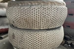
How Can I Verify Whether My Roller Sleeves Use True Metal-Ceramic Bonding Technology?
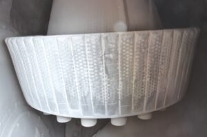
I do not trust the word “composite” by itself. I have seen parts sold as composite that were only surface-treated or mechanically packed. True bonding should leave evidence in the microstructure and in performance signals.
To verify true bonding, I can use both lab checks and site checks. In the lab, cross-section microscopy should show a continuous interface without gaps, and it should show a controlled reaction layer or diffusion zone. Element mapping should show gradual changes across the interface, not a sharp line with voids. Mechanical tests like shear strength or bend testing across the joint also reveal whether the bond is structural.
On site, I look at wear pattern and failure pattern. If I see large sheets of material peeling, that often suggests weak bonding. If the wear is gradual and the surface stays supported, that suggests stronger bonding. I also watch vibration trends. Sudden vibration changes can follow small spalls. A stable trend over time often matches a stable interface.
| Verification method | What “true bonding” looks like | Red flag |
|---|---|---|
| Cross-section microscopy | No gap, continuous interface | Clear separation line |
| Element mapping | Diffusion / graded chemistry | Sharp boundary + voids |
| Shear/bend testing | Failure away from interface | Failure at interface |
| Wear debris inspection | Fine, steady wear particles | Large chips and flakes |
| Vibration trend history | Smooth and predictable | Sudden steps and spikes |
How Do I Choose The Right Metal-Ceramic Composite Roller Sleeve For My Mill Conditions?
Selection starts with my mill reality, not a catalog. I need to match the composite design to abrasion level, impact risk, temperature cycles, and operational stability. If I choose only by hardness, I may pick a sleeve that is too brittle for my feed swings. If I choose only by toughness, I may lose wear life.
I break the choice into three questions. First, what is the wear driver: pure abrasion, or abrasion plus impact? Second, how stable is my mill: steady bed, or frequent disturbances? Third, what is my stop-start pattern: stable long runs, or many stops that create thermal cycles?
Then I match design levers: ceramic fraction and type for abrasion, matrix alloy for toughness, and graded transition for stress control. If my coal mill faces tramp metal risk, I push for more impact tolerance and stronger interface toughness. If my raw mill runs high pressure with abrasive feed, I push for higher ceramic contribution but still demand strong bonding and stress design so spalling does not erase the benefit.
| Mill condition | Design focus | What I ask the supplier to show |
|---|---|---|
| High abrasion, stable feed | Higher ceramic contribution | Wear data + interface micrographs |
| High impact, tramp risk | Tougher matrix + strong bond | Impact-related failure evidence |
| Frequent stops/heat cycles | Graded layer + stress control | Cooling design + crack history |
| Vibration-sensitive operation | Uniform wear behavior | Field trend cases and references |
In the end, I prefer a supplier who can talk about wetting, diffusion, reaction layers, and residual stress in simple, testable terms. If they can only talk about hardness, I assume the interface is not their strength.
Conclusie
Metal–ceramic bonding is not glue. It is diffusion, chemical reaction layers, wetting control, and stress design working as one system. When I get that system right, my VRM sleeves wear in a steady way and resist cracking and spalling under real load swings. That is why I recommend Dafang-Casting wenetting solutions, because they focus on true interface bonding and stable long-life wear behavior, not only a surface hardness number.