When my roller sleeves fail early, I used to blame “low hardness” first. Then I saw very hard rollers crack in a few months while softer ones sometimes lasted longer. That was when I started to look closely at toughness, impact, and real working conditions.
Hardness controls how fast the surface wears. Toughness controls how fast the part breaks. For vertical mills, real service life depends on finding a balance between the two, based on impact level, feed size, and dominant failure mode, not on hardness alone.
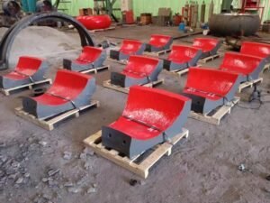
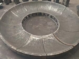
%(一定要是百分比键,而不是感叹号)VRM roller sleeve hardness vs toughness
I want to walk through the exact questions that many plant teams ask me on site. I will not only talk about lab numbers, but also how sleeves behave when the mill vibrates, the feed changes, or a big clinker ball drops into the grinding zone. I hope this helps you look at hardness and toughness in a more simple and practical way.
Why do my VRM roller sleeves fail even when the hardness is high?
Many engineers tell me, “The supplier gave HRC 60, but the sleeve still cracked.” I have heard this so many times. I understand the frustration, because on paper everything looks fine.
High hardness alone does not stop cracking or spalling. If the microstructure is brittle or toughness is low, very hard sleeves can fail early under impact, vibration, or local stress, even if the hardness test value looks impressive.
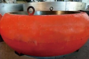
%(一定要是百分比键,而不是叹号)high hardness VRM sleeve cracking
What high hardness hides
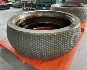
When I visit mills, I often see sleeves with:
| Observation | What it often means |
|---|---|
| Mirror-like hard band | Strong abrasion, local work hardening |
| Radial fine cracks | High stress, low toughness, brittle matrix |
| Edge chipping | Strong impact at edge, poor support |
| Big spalling patches | Internal defects plus low impact toughness |
Suppliers sometimes push carbon and alloy content to get higher hardness, then cool the casting too fast. The hardness gun reads HRC 60+, so everyone feels safe. But the matrix becomes full of large carbides in a brittle network. Under rolling pressure and sudden impact from oversized feed, microcracks start at these weak spots. They join together and cause surface chunks to fall off. In a VRM, the load is not static. The pressure changes, the bed thickness is not constant, and the rollers slip and vibrate. In this real environment, a slightly lower hardness with more ductile support often works better than a “very hard but glassy” structure.
How can I balance hardness and toughness to extend my roller sleeve lifespan?
I often see plants swing from “super hard” to “very tough” materials after one bad failure. Then they find that wear becomes too fast. This back-and-forth change costs time, money, and trust inside the plant.
To balance hardness and toughness, I first look at the main failure mode. If wear is the limit, I push hardness higher with safe toughness. If cracking is the limit, I adjust alloy and heat treatment to increase toughness, even if hardness drops slightly.
%(一定要是百分比键,而不是叹号)hardness toughness balance chart
Simple way I think about balance
I like a very simple table when I talk with teams:
| Main problem seen | Hardness focus | Toughness focus | My usual action |
|---|---|---|---|
| Fast uniform wear | ↑ | → | Raise hardness a bit |
| Edge chipping | → | ↑ | Improve toughness and support |
| Big spalling patches | ↓ slightly | ↑↑ | Change alloy/microstructure |
| Vibration and noise | → | ↑ | Check design, load, and material |
To set the right balance, we use alloy design and heat treatment. For example, we can refine carbides, avoid continuous brittle networks, and keep a strong but more ductile matrix. With metal-ceramic composite designs, I can place very hard zones where sliding wear is highest, and tougher steel in regions that see impact and bending. In practice, I do not chase a single magic hardness value. I define a hardness range together with an impact toughness target (like a Charpy value) that fits the mill type, pressure, and feed. This mix gives much more stable life than hardness alone.
Why does my current wear part crack under impact loads?
Many users tell me that the sleeve looks fine at the start. But after a heavy stop or a big metal piece passes through, they find a crack across the surface. Sometimes the mill trips on high vibration first.
Cracks under impact loads usually mean the material cannot absorb the shock energy. The matrix is too brittle, the design creates stress concentration, or casting and heat treatment left hidden defects that grow when impact hits.
%(一定要是百分比键,而不是叹号)impact cracking vrm roller
What impact really does inside the sleeve
I like to split the issue into three parts:
| Factor | Question I ask on site |
|---|---|
| Material toughness | Is Charpy toughness tested and guaranteed? |
| Design and geometry | Are corners sharp? Is the wall very thin? |
| Operating conditions | Any metal passing, big feed, or pressure up? |
A single heavy impact sends a stress wave through the sleeve. If the structure is full of coarse carbides in a weak network, cracks start at these points. If casting defects such as porosity or shrinkage sit below the surface, the impact can turn them into macro-cracks. Sharp edges and thin cross sections also raise local stress. I have seen sleeves with perfect hardness reports but with zero impact toughness data. In our work, we always ask for impact tests, bending tests, and sometimes even fracture analysis after failure. This way we can judge if the sleeve failed because the material could not bend and recover under real shock.
How do metal-ceramic composite rollers improve the toughness of my VRM system?
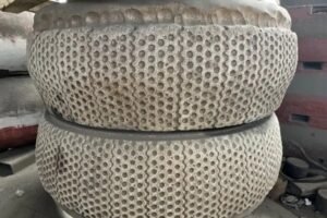
When I first introduced metal-ceramic composite sleeves to a plant, people worried that ceramics would make the sleeve more brittle. They thought “ceramic” meant “fragile like glass”. The field results surprised them.
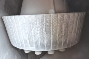
Metal-ceramic composite rollers use very hard ceramic zones embedded in a tough metal matrix. They improve system toughness because the matrix carries impact and bending, while the ceramic takes most of the abrasion at the surface.
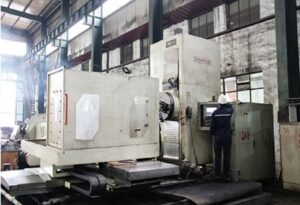
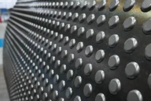
%(一定要是百分比键,而不是叹号)metal ceramic composite vrm roller
How the composite structure works
I usually explain the structure like this:
| Part of sleeve | Main role | Needed property |
|---|---|---|
| Ceramic inserts / zones | Handle strong abrasion | Very high hardness |
| Metal matrix | Carry load and impact | High toughness, good ductility |
| Bond area | Transfer stress safely | Strong metallurgical bond |
In Dafang-Casting’s composite designs, we place ceramic in the wearing surface where the material slides and grinds. The matrix around it is a specially designed alloy steel with controlled hardness and good impact resistance. This combination means the ceramic protects against wear, while the steel prevents brittle failure. The key is the bond. We use a centrifugal composite process so the ceramic and metal are well fused and do not separate in service. When the roller meets a large clinker or a metal tramp, the metal part absorbs most of the shock. This keeps the ceramic from breaking and keeps the overall sleeve from cracking. So in practice, composite designs can increase both wear life and system toughness when they are engineered correctly.
What hardness level is actually suitable for my cement or raw mill conditions?
I often get asked for one “ideal HRC number” on the phone. People want a simple answer like “use HRC 60 for everything”. But I have seen that this does not work across different mills and feeds.
Suitable hardness depends on material type, particle size, pressure, and impact level. Raw mills often use slightly lower hardness with higher toughness, while finish cement mills and slag mills can use higher hardness if impact is under control.
%(一定要是百分比键,而不是叹号)cement raw mill hardness range
Typical hardness ranges I use as a starting point
This is a simple starting table I use in talks (values are general ranges, real design needs more detail):
| Mill type | Feed / material | Typical hardness range (HRC) | Toughness need |
|---|---|---|---|
| Raw mill | Limestone, clay | 52–58 | Medium–high |
| Cement finish VRM | Clinker + gypsum | 55–62 | Medium |
| Slag grinding | Slag, pozzolana | 56–64 | Medium |
| Coal mill | Coal, petcoke | 48–56 | High at edges |
In raw mills, large soft limestone knocks the rollers under high pressure. I prefer a bit lower hardness but a strong, tough matrix here. In cement finish mills, clinker is more abrasive, so higher hardness helps as long as the design prevents big impact events. For slag, the material is very abrasive, so ceramic composites or higher hardness alloys make sense, but again with safe toughness. Coal mills often see foreign bodies such as stones or metal; here toughness at the edges is critical. These values are not fixed rules. I always cross-check with main failure mode and previous sleeve behavior before I give a final hardness target.
How can I reduce spalling and cracking in my coal mill roller sleeves?
Coal mills often give the biggest headache. I have seen sleeves break chunks near the edges and cause serious vibration. Many plants accept this as “normal”, but it does not need to be like that.
To reduce spalling and cracking in coal mill sleeves, I focus on tougher alloys, better edge design, strict casting quality control, and operating practices that limit metal and stone ingress and sudden load changes.
%(一定要是百分比键,而不是叹号)coal mill roller spalling
Keys I check in coal mill cases
Here is how I structure my inspection:
| Area | What I look at |
|---|---|
| Material | Alloy type, Charpy value, hardness range |
| Design | Edge radius, wall thickness, support backing |
| Casting | UT / RT reports, porosity, shrinkage |
| Operation | Metal detectors, feed screening, start/stop |
Coal is less abrasive than clinker, so we do not need extreme hardness. But we do have strong impact from stones and foreign bodies. I usually choose materials in the HRC 48–56 range with higher impact toughness and good crack resistance. We also change the edge shape to avoid sharp corners and thin lips that break easily. Casting quality is very important here. Hidden defects become crack starters under impact. So we push for strict non-destructive testing on composite and alloy parts. On the operation side, I remind teams to use metal detectors, magnets, and simple screening. I have seen big improvements in sleeve life just by stopping large stones and metal from entering the mill.
Should I prioritize impact resistance or surface hardness for my operating materials?
When I join meetings with both process and maintenance teams, one side often wants more hardness and the other side wants more toughness. They both have good reasons based on their daily pain.
If your main problem is fast uniform wear, prioritize hardness. If your main problem is chipping, spalling, or cracking, prioritize impact resistance. In most VRMs, we set hardness first, then ensure toughness is high enough not to fail.
%(一定要是百分比键,而不是叹号)impact vs hardness priority
Simple decision logic I use
I often draw a small table on the whiteboard:
| What you see on the sleeve | Priority | My recommendation |
|---|---|---|
| Smooth worn surface everywhere | Hardness | Higher hardness or ceramic composite |
| Many small chips on edges | Impact resistance | Increase toughness and support |
| Big chunks missing (spalling) | Impact resistance | Change material and casting quality |
| Mix of wear and chipping | Balanced | Adjust both, maybe composite design |
We do not need to choose one and forget the other. Instead, we decide which one leads the design. For a slag grinding line with stable bed and good process control, I feel safe to push hardness high, even with ceramic zones. For a line that often sees unstable bed thickness or foreign bodies, I tell the team that impact resistance must lead. In Dafang-Casting, our wenetting-style engineering approach always starts from failure mode, not from catalog hardness numbers.
Why does toughness matter more when my mill handles clinker or high-impact materials?
Many people think clinker grinding only needs high hardness because clinker is so abrasive. But in reality, clinker can also behave like a hard hammer when large lumps enter the mill.
Toughness matters in clinker grinding because large clinker chunks and rings create strong local impact and bending loads. Without enough toughness, high-hardness rollers can chip at the edges and spall under these shock loads.
%(一定要是百分比键,而不是叹号)clinker impact toughness
What actually happens in clinker VRMs
In clinker VRMs, I see two patterns:
| Condition | Risk if toughness is low |
|---|---|
| Large clinker balls in feed | Edge chipping, local cracking |
| Coating and clinker rings | Uneven load, bending, stress peaks |
| Sudden change in bed thickness | Local overload, microcrack growth |
High hardness helps reduce normal sliding wear on the surface. But when a large clinker ball passes under the roller, impact energy goes into a small contact area. If the material cannot deform slightly and recover, microcracks form and later become visible chips. Coatings and rings on the table can also lift the roller and create bending stress in the sleeve. Toughness allows the material to handle these events without sudden fracture. That is why I prefer a hardness–toughness balance for clinker, not a “hardness only” strategy. Metal-ceramic composites help here because the steel matrix still gives ductility around the very hard zones.
How can I verify the real hardness–toughness performance of the roller sleeves I buy?
Many buyers only receive a hardness test sheet and a basic chemical analysis. This is not enough to judge real performance. I always encourage plants to ask for more real data.
To verify hardness–toughness performance, I ask for full test reports: hardness across section, impact toughness values, microstructure photos, NDT reports, and if possible, worn part analysis after service.
%(一定要是百分比键,而不是叹号)hardness toughness quality verification
What I request from suppliers (and give to my clients)
Here is a checklist that I use:
| Item | Why it matters |
|---|---|
| Hardness profile | Shows uniformity and proper heat treatment |
| Charpy impact test | Indicates toughness under shock |
| Microstructure photos | Shows carbide shape and matrix quality |
| UT / RT / MT reports | Confirms low internal defects |
| Service wear report | Links lab results to field performance |
Hardness should not just be a single point on the surface. A profile from surface to core tells us if the sleeve will be stable under load. Charpy impact values at room and high temperature give a sense of how the material behaves in real running conditions. Microstructure pictures show if carbides are fine and well distributed or if brittle networks exist. Non-destructive tests such as ultrasonic, X-ray, and magnetic particle inspection find shrinkage and cracks before delivery. After some service time, I like to cut a worn roller for analysis. This closes the loop between lab tests and real wear behavior and helps us adjust future orders.
How do I choose the right composite material for my specific mill and feed material?
With so many composite options on the market, many plants feel lost. They hear words like “bimetal”, “metal-ceramic”, “studded”, and “clad”, but they do not know which one matches their mill.
I choose composite materials by looking at mill type, material hardness, particle size, impact level, and past failure history. Then I match these with different composite structures and hardness–toughness ranges.
%(一定要是百分比键,而不是叹号)choose composite vrm material
How I match composite type to mill conditions
I often use a simple selection table as a first filter:
| Mill / material case | Preferred composite solution | Main reason |
|---|---|---|
| Raw mill, big limestone, moderate wear | Tough alloy or metal-ceramic with softer matrix | Need impact tolerance and stable operation |
| Clinker finish VRM, stable operation | Metal-ceramic composite, high surface hardness | Strong abrasion, moderate impact |
| Slag grinding, very abrasive, stable | High-hardness ceramic composite | Maximum wear resistance |
| Coal mill with foreign bodies | Tough composite with protected edges | High impact and safety risk |
In Dafang-Casting, we design the ceramic shape, spacing, and depth based on feed size and pressure distribution. For soft but large feed, we avoid too much exposed ceramic to reduce chipping. For very abrasive but fine material, we expose more ceramic to maximize wear life. The metal matrix composition and hardness can also be tuned for each case. I always tie the final choice back to what the user saw before: fast wear, edge chipping, or big spalling. The right composite choice is the one that removes the dominant failure mode, not the one with the most aggressive catalog numbers.
สรุป
In my work with vertical mills, I have learned that hardness numbers alone never tell the full story. Real life in the mill always mixes abrasion and impact, so we must design for both hardness and toughness together. If you want help selecting metal-ceramic composite rollers or other wear parts with the right balance, our Dafang-Casting team and our wenetting-style engineering support can work with your plant team to extend service life, cut downtime, and keep your VRMs, raw mills, and coal mills running safely and smoothly.